
4.Application Scenarios
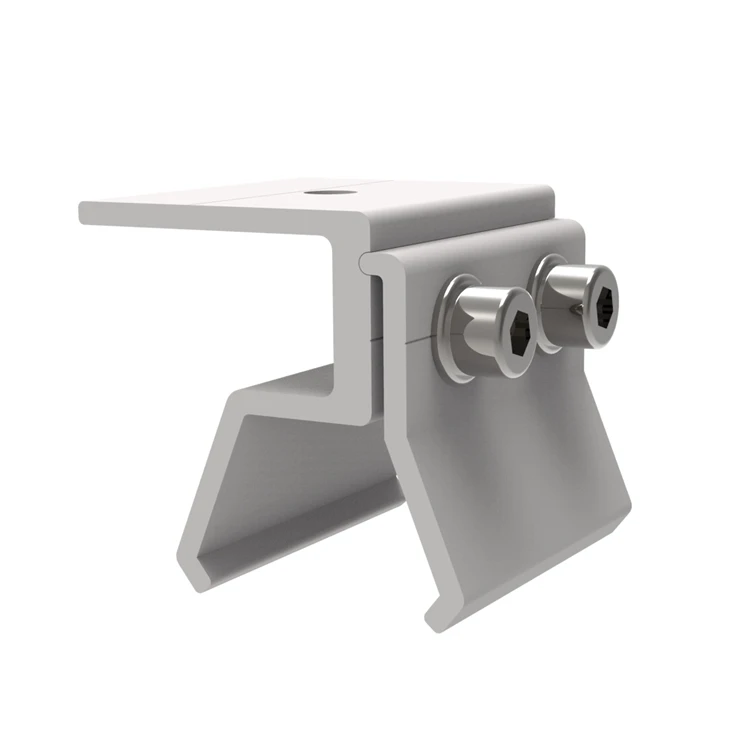
On cement top floor


Product Compatibility & Advantages:
Key Benefit: Aluminum alloys offer an excellent strength-to-weight ratio, ensuring structural stability while being easy to transport and install.It can be installed by drilling holes directly into a concrete roof, or by casting concrete blocks on-site.The minimum order quantity is low, allowing for flexible handling.
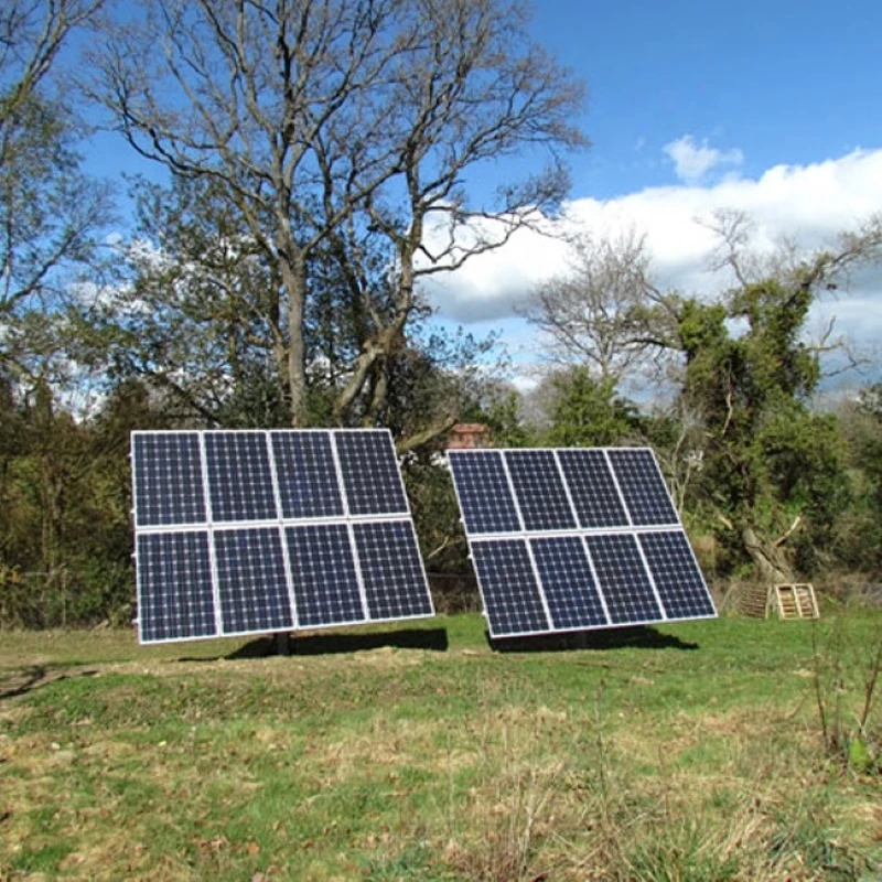
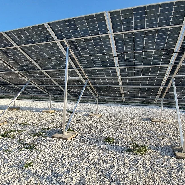
On the ground


Product Compatibility & Advantages:
Key Benefit:Aluminum ground mounts are suitable for diverse landscapes, including uneven or sloped ground, with adjustable designs to ensure proper leveling and stability.
5.Installation&Maintenance Guide
Part 1: Installation Guide
Preparation Before Installation:
Site Survey and Drawing Confirmation: Verify the construction drawings, confirming the bracket layout, foundation points, array tilt angle, and azimuth angle. Clear the site to ensure there are no obstacles.
Material Inventory: Check the model, quantity, and quality of all components (columns, diagonal beams, crossbeams, connectors, fasteners, etc.) against the checklist, ensuring there is no damage or deformation.
Tool Preparation:
Measuring Tools: Total station/theodolite, level, tape measure, spirit level, chalk line.
Installation Tools: Impact drill (for chemical or expansion bolt foundations), torque wrench (crucial), adjustable wrench, socket wrench set, rubber mallet, screwdriver.
Safety Equipment: Safety helmet, insulated gloves, safety shoes, safety harness (for working at heights).
Installation Process (Step-by-step instructions, recommended to be used in conjunction with diagrams):
Step 1: Foundation Re-measurement and Positioning
Using measuring instruments, accurately lay out the foundation according to the drawings, marking the center position of all column bases.
Check the position, elevation, and levelness of the embedded parts or precast foundations. The error must be within the allowable range specified in the standards (usually horizontal error ≤ ±3mm, elevation error ≤ ±10mm).
Diagram Key Points: Indicate the reference points, layout paths, and final positioning points on the drawing.
Step 2: Column Installation
Connect the columns to the embedded plates or anchor bolts on the foundation.
Key: Use a spirit level or level instrument to ensure the verticality of each column. Initially tighten the bolts.
Diagram Key Points: Show the column verticality testing method.
Step 3: Main Beam (Diagonal Beam) Installation
Fix the diagonal beams to the top of the two rows of columns using connectors.
Adjust the angle of the diagonal beams to meet the design tilt angle requirements. Use an angle meter or verify according to pre-calculated dimensions.
Diagram Key Points: Indicate the design tilt angle (e.g., 23°, 30°, etc.).
Step 4: Crossbeam (Purlin) Installation
Arrange the crossbeams perpendicular to the diagonal beams, parallel to each other at the spacing shown in the drawings, and fix them with bolts. This is the direct structure supporting the photovoltaic modules. It is crucial to ensure that the top surfaces of all beams are in the same plane to guarantee a level installation of the modules.
Diagram key points: Shows beam spacing (corresponding to module width) and coplanar adjustment.
Step 5: Bracket Leveling and Final Tightening
This is the most critical step. Use a spirit level or string line method to verify the overall flatness of the entire array.
Finely adjust the bolts at the connections to eliminate local warping or unevenness.
Use a torque wrench to finally tighten all connecting bolts to the torque value specified in the design. (For example, M8 bolts typically require 20-25 N·m; strictly follow the manufacturer's instructions).
Diagram key points: Indicates key tightening points and torque values.
Step 6: Lightning Protection Grounding Connection
Reliably connect the main body of the bracket to the grounding trunk line as required by the design, usually using galvanized flat steel or copper stranded wire.
Check that the connection points are secure and that the resistance meets the specifications (usually required to be ≤4Ω).
Step 7: Installation Inspection and Cleaning
Thoroughly check all bolt tightening, structural stability, and whether there is any installation damage to the anti-corrosion coating.
Clean dust and metal debris from the surface of the bracket.
Part Two: Daily Inspection and Maintenance
1. Daily/Weekly Inspection Points:
Visual Inspection: Visually inspect the support structure for any obvious deformation, tilting, or abnormal displacement.
Fastener Inspection: Randomly check key areas (such as the base of the columns and diagonal beam connections) for any signs of loose bolts.
Component Surface Inspection: Observe the photovoltaic modules installed on the support structure for any cracks or deformation caused by support structure issues.
Foundation Inspection: Check the ground around the foundation for severe soil erosion, settlement, or cracking.
2. Regular Maintenance Cycle and Content:
Quarterly Maintenance:
Systematically check the tightening torque of all bolts, especially after strong winds, rain, or snow. Use a torque wrench for retightening.
Inspect the anti-corrosion coating. For minor scratches caused during transportation or installation, use anti-rust paint or aluminum alloy repair agent for touch-up.
Clean up weeds and debris accumulated at the base of the support structure that may affect drainage or cause corrosion.
Annual Comprehensive Maintenance:
Perform all quarterly maintenance items.
Comprehensively check the verticality and horizontality of the support structure using instruments, comparing the measurements with initial data to determine if there is any settlement or deformation.
Check all welds (if any) for cracks.
Thoroughly inspect and test the continuity and grounding resistance of the grounding system.
Prepare a written maintenance report, documenting the problems found and the corrective actions taken.
Part Three: Precautions and Troubleshooting Common Problems
Installation Precautions (Text Format):
Torque is critical: A torque wrench must be used! Under-tightening will lead to structural loosening, and over-tightening may damage the aluminum alloy threads or cause stress concentration. Strictly follow the torque values provided by the manufacturer.
Avoid mixing materials: It is strictly forbidden to allow aluminum alloy support components to come into direct contact with carbon steel components to prevent electrochemical corrosion. Insulating gaskets or galvanized steel connectors must be used.
Lifting and handling: Use soft slings during lifting to avoid scratching the surface coating with hard objects such as steel ropes. Handle with care during transportation to prevent bumps and collisions.
On-site cutting and drilling: Avoid on-site cutting and drilling unless absolutely necessary. If the procedure is necessary, the exposed metal cuts must be treated with anti-corrosion sealant after completion (such as applying zinc-rich paint or a special sealant).
Weather Warning: Installation should be suspended before the onset of severe weather (strong winds, heavy rain, lightning), and the temporary fixings of the already installed parts should be checked for security.
6.FAQ – Frequently Asked Questions
Q1: What type/specifications of solar panels are suitable for aluminum alloy brackets?
A: Aluminum alloy brackets are highly versatile and suitable for most mainstream solar panels currently available.
Q2: Is professional qualification required to install aluminum alloy brackets?
A: It is strongly recommended that installation be carried out by a professional team.
Q3: What is the product and performance warranty?
A: The standard warranty period is 10 years, with a design service life of up to 25 years.
Q4: What is the load-bearing capacity of aluminum alloy brackets? Can they withstand strong winds and heavy snow?
A: Yes, but the load-bearing capacity depends on the specific design.
Q5: What are the main advantages and disadvantages of aluminum alloy brackets compared to galvanized steel brackets?
A: Advantages:
1)Lightweight: Easier installation, lower transportation costs, and relatively lower foundation requirements.
2)Strong corrosion resistance: Inherently corrosion-resistant, no hot-dip galvanizing required, performs better in coastal and high-humidity areas.
3)Maintenance-free: Requires virtually no rust prevention maintenance, resulting in lower life cycle costs.
4)Aesthetic appeal: Diverse surface treatment options, resulting in a more refined appearance.
Disadvantages:
1)Initial cost: The unit price of the material is usually higher than that of ordinary galvanized steel.
2)Strength and deflection: Under the same cross-section, its stiffness and strength may be weaker than steel. Therefore, under large spans or extreme load conditions, a more optimized structural design or slightly larger cross-section may be needed to compensate..
Q6: How should the foundation be treated? What are the options?
A: The foundation choice depends on the geology, cost, and construction conditions:
1)Concrete foundation: The most stable and reliable, suitable for most soil types. Includes independent foundations, strip foundations, etc.
2)Screw piles: Fastest installation, no curing required, minimal soil disturbance, suitable for soft soil, and can be easily removed and recycled.
3)Driven piles/micropiles: Suitable for hard ground such as rock.
Q7:Is daily maintenance truly "zero maintenance"? What needs to be done? A: Although not completely "maintenance-free," the maintenance required is minimal:
1)Regular inspections (recommended every six months or after strong winds/heavy snowfall): Visually inspect the structure for integrity and check for loose bolts (especially during the first year after installation).
2)Annual inspection: Systematically check key bolts with a torque wrench; verify the reliability of grounding connections; clean any weeds or debris accumulated at the base of the support structure to prevent moisture buildup or impaired heat dissipation.
Unlike steel structures, regular painting for rust prevention is not required.
7.Customer Cases
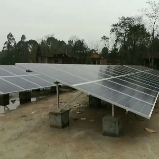
Case 1: Solar Ground Project – Lebanon

- Location: Lebanon
- Project Scale:1MW Cement Block Foundation Ground Mount
- Application: Commercial Usage
Performance & Results:
Aluminum naturally forms a protective oxide layer, providing outstanding resistance to rust and environmental degradation, even in humid or coastal areas.With minimal maintenance requirements, aluminum supports can withstand harsh weather conditions (UV exposure, temperature fluctuations, etc.) and maintain performance over decades.
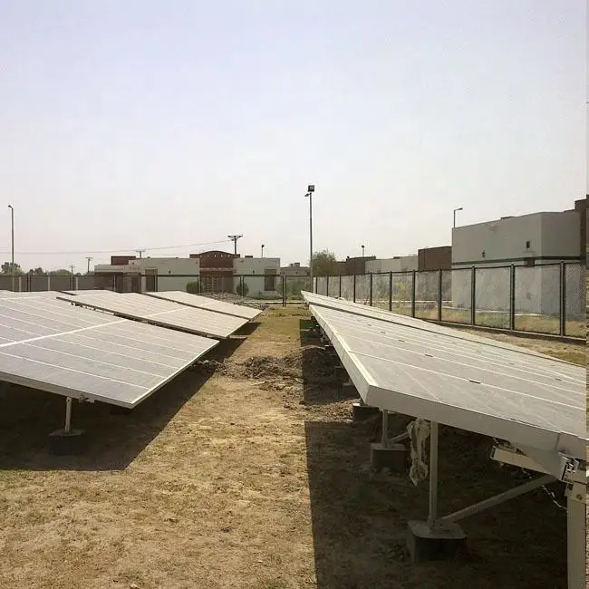
Case 2: Solar Ground Project--Pakistan

- Location: Pakistan
- Project Scale: 1.2MW Ground Mount System
- Application:National Grid power generation requirements
Performance & Results:
The power generation process is emission-free, pollution-free, and noiseless, making it a truly green energy source. Every kilowatt-hour of electricity generated is equivalent to reducing fossil fuel consumption and the corresponding emissions of carbon dioxide, dust, and sulfur oxides.The lightweight nature and modular designs simplify on-site assembly, reducing labor costs and installation time.
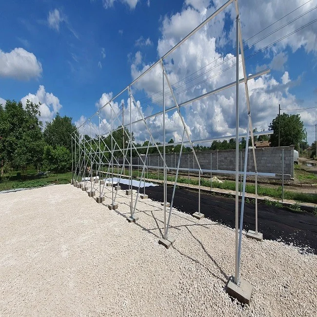
Case 3: Solar Project--Bulgaria

- Location: Bulgaria
- Project Scale: 40KW Ground Mounting System
- Application: Off-grid system
Performance & Results:
The electricity generated by the system is prioritized for self-consumption, directly offsetting the electricity purchased from the grid and significantly reducing electricity bills. Any surplus electricity can be "sold" back to the grid, with billing handled through a bidirectional meter, further increasing revenue or reducing electricity costs.